Labels

Search This Blog

24 October 2023

Brake Application At Front Axle Function - Mercedes Benz Actros

Requirements

  • Vehicle moving.
  • Max. supply pressure in circuit 1 and 2 (V1, V2).
  • No faults indicated in driver information system (FIS) display in instrument (INS). 
  • Electronics of brake system (BS) operational.
V1 System pressure (circuit 1)
V2 System pressure (circuit 2)
NV Accessory supply pressure

a System pressure
b Brake pressure
c Redundant brake pressure

12.08 Rpm sensor
13.07 Brake value sensor
16.07 Proportioning relay valve
20.02 Single-circuit diaphragm brake cylinder
22.01 Combination brake cylinder
30.03 Pressure limiting valve with vent
31.08 Drive-axle axle modulator
33.07 3/2-way valve for auxiliary braking effect
33.08 Front axle redundancy valve
33.10 Rear axle redundancy valve
45.01 ABS solenoid valve

A11 Electronic brake system (EBS) control unit
FB Parking brake

Function sequence

  1. The brake pedal is depressed :
    • The sensors in the brake value sensor (13.07) register the driver's braking requirements electrically for the brake control (BS) control unit (A11).
    • Via connection 22, the pneumatic component of the brake value sensor (13.07) actuates the closed front axle redundancy valve (33.08) with a redundant control pressure corresponding to the pedal travel.
  2. The electronics of the brake control (BS) control unit (A11) uses the electric signals from the brake value sensor to calculate the specified deceleration for the front and rear axle.
  3. The brake control (BS) control unit (A11) uses the specified deceleration signal to actuate the proportioning relay valve (16.07) at the front axle and causes it to apply the brake pressure.
  4. Front axle 
    • Right : The brake pressure is fed into the right-hand single- circuit diaphragm brake cylinder (20.02) on the front axle via the opened ABS solenoid valve (45.01); the wheel is braked.
    • Left : The brake pressure is fed into the left-hand single- circuit diaphragm brake cylinder (20.02) on the front axle via the 3/2-way auxiliary brake valve (33.07) and the opened ABS solenoid valve (45.01); the wheel is braked.
    • If the front axle brake circuit fails, the 3/2-way auxiliary brake valve (33.07) boosts the braking effect at the rear axle. As long as brake pressure from the proportioning relay valve (16.07) is available at connection 12 of the 3/2- way auxiliary brake valve (33.07) during the braking operation, the valve will remain inoperative and the brake pressure can flow through freely.
  5. To calculate the actual deceleration and the wheel slip, the brake control (BS) control unit (A11) evaluates the signals from the rpm sensors (12.08) at the wheels and from the pressure sensors in the proportioning relay valve (16.07) throughout the entire braking operation.
    • If the actual deceleration deviates from the specified deceleration, the brake control (BS) control unit (A11) causes the proportioning relay valve (16.07) to reduce or increase the brake pressure.
Materi terkait :

Brake Application At Rear Axle Function - Mercedes Benz Actros

Requirements

  • Vehicle moves.
  • System pressure (V1, V2) in circuit 1 and circuit 2. 
  • The electric brake control is operational.
  • No faults are indicated in the driver information system (FIS) display in the Instrument (INS).
V1 System pressure (circuit 1)
V2 System pressure (circuit 2)

a System pressure
b Brake pressure
c Redundant brake pressure
d Control pressure

12.08 Rpm sensor
13.07 Brake value sensor
22.01 Combination brake cylinder
31.08 Drive-axle axle modulator
33.08 Front axle redundancy valve
33.10 Rear axle redundancy valve

A11 Electronic brake system (EBS) control unit

FB Parking brake

Function sequence

  1. The brake pedal is depressed.
  2. The sensors in the brake value sensor (13.07) register the pedal travel electrically for the brake system (BS) control unit (A11).
  3. The brake system (BS) control unit (A11) uses the pedal travel to compute the specified deceleration of the vehicle.
  4. Vehicles without code (ZX2) EPB II Via connection 21 the pneumatic component of the brake value sensor (13.07) directs a redundant brake pressure (c) corresponding to the pedal travel to the closed rear axle redundancy valve (33.10).
  5. The brake control (BS) control unit (A11) uses the calculated specified deceleration to actuate the electronics of the drive axle-axle modulator (31.08 or 31.13).
  6. The electronics of the drive-axle axle modulator (31.08 or 31.13) convert the control command from the brake control (BS) control unit (A11) into electrical control signals for the internal valves and causes them to apply the brake pressure (b).
  7. Supply pressure (a) is directed from connections 11 and 12 as brake pressure (b) though connections 21 and 22 of the drive-axle axle modulator (31.08 or 31.13) into the combination brake cylinders (22.01) of the rear wheel brakes; the wheels are braked.
  8. During the entire brake application, the electronics of the drive-axle axle modulator (31.08 or 31.13) record the values from the internal pressure sensors and the signals from the rpm sensors (12.08) on the rear wheels and transmits these to the brake control (BS) control unit (A11).
  9. To calculate the actual deceleration and the wheel slip, the brake control (BS) control unit (A11) evaluates the signals and values of the drive-axle axle modulator (31.08 and 31.13). If the actual deceleration deviates from the specified deceleration, the brake control (BS) control unit (A11) causes the drive-axle axle modulator (31.08 or 31.13) to reduce or increase the brake pressure (b).
  10. The driver releases the brake pedal and the brake application is complete. The applied brake pressure (b) and the applied redundant brake pressure (c) are released again through ventilation connection 3.

In the case of ABS control, the internal valves of the drive-axle axle modulator (31.08 or 31.13) perform the "pressure buildup", "pressure hold" and "pressure release" functions in the same way as the ABS solenoid valves on the front axle.

Materi terkait :

Telligent Brake System Function - Mercedes Benz Actros

General - Vehicles without code (ZX2) EPB II

Model 930-934

1 - Trailer/semitrailer data interface
2 - ASIC data bus

E - Electrical component
P - Pneumatic component

a - System pressure 
b - Brake pressure
c - Redundant brake pressure
V1 - System pressure (circuit 1)
V2 - System pressure (circuit 2)
V3 - System pressure (circuit 3)

13.07 - Brake value sensor
16.07 - Proportioning relay valve 
18.07 - Trailer control valve
20.02 - Single-circuit diaphragm brake cylinder
22.01 - Combination brake cylinder 
31.08 - Drive axle axle modulator
33.08 - Front axle redundancy valve
33.10 - Rear axle redundancy valve
35.02 - Coupling head for supply
35.03 - Coupling head for brake 
45.01 - ABS solenoid valve

The Telligent brake system is an electronically monitored and electrically controlled pneumatic brake system. The Telligent brake system consists of a purely pneumatic dual- circuit brake system, which is actuated by the electric brake control. The electric brake control overlays the conventional, purely pneumatically operating control of the service brake and adds to it the following functions:

  • Antilock brake system (ABS)
  • Acceleration Slip Regulation (ASR)
  • Automatic load-dependent brake pressure control (ALB)
  • Hill holder
  • Brake Assist System

The stability control (SR) function can be integrated in the Telligent brake system as an option. When a trailer or semitrailer is attached, the Telligent brake system is also responsible for controlling the trailer brake system. The pneumatic and electrical control capabilities of the trailer brake mean that trailers or semitrailers with purely pneumatic or electropneumatic brake system can be connected without problem.

The individual regulation of brake pressure for the wheel brakes on the front and rear axles forms the basis for all the functions of the Telligent brake system. The brake circuits of the front axle, the rear axle and the trailer or semitrailer are each safeguarded by a pneumatic safety circuit referred to as the redundancy circuit.

In the event of partial or total failure of the electric brake control, the wheel brakes are actuated with the relevant redundant brake pressure (c) by purely pneumatic means.


Electrically regulated brake application 

The travel of the brake pedal is registered by two sensors in the brake value sensor (13.07) and is converted into electrical values for the brake system (BS) control unit (A11). The brake control (BS) control unit (A11) uses the values to compute the specified deceleration and the brake pressure (b) required for this. The brake pressure (b) necessary for producing the specified deceleration is transmitted over the brakes CAN (CAN 6) by control commands from the brake control (BS) control unit (A11) to the drive axle axle modulator (31.08 or 31.13). The electronics in the brake control (BS) control unit (A11) regulate the brake pressure (b) at the front axle and the electronics in the drive axle axle modulator (31.08 or 31.13) regulate the brake pressure (b) at the rear axle.

The calculated brake pressure (b) is applied at the front axle via the proportioning relay valve (16.07) and at the rear axle direct by the drive axle axle modulator (31.08 or 31.13). The pressure sensors in the proportioning relay valve (16.07) and in the drive axle axle modulator (31.08 or 31.13) monitor the applied brake pressure (b).

At the same time, the brake control (BS) control unit (A11) uses the signals from the rpm sensors (B30, B31, B32, B33) on the axles to calculate the rate of rpm change at the wheels. The brake control (BS) control unit (A11) uses the rpm change to detect the actuati deceleration of the vehicle and the wheel slip.

If there is a difference between the actual deceleration and the specified deceleration, braking is adjusted by an appropriate control command.

  • Differential slip control

Differential slip control replaces the conventional ALB function. Differential slip control starts at moderate wheel speed differences.

  • ABS control

If one or more wheels shows a tendency to lock up when high rpm differences occur, the brake system (BS) control unit (A11) triggers the familiar ABS control.

  • ASR control

If one or more of the drive wheels shows a tendency to spin when high rpm differences occur, the brake system (BS) control unit (A11) triggers the familiar ASR control.

A3 - Drive control (FR) control unit 
A6 - Engine control (MR) control unit 
A7 - Base module (GM)
A11 - Telligent brake system (BS) control unit
A28 - Drive axle axle modulator
A64 - Front module (FM)
A65 - Rear module (HM) 
A68 - Master switch module 4
A77 - Dash support switch module 1
B30 - Left front axle rpm sensor
B31 - Right front axle rpm sensor
B32 - Left 1 st rear axle rpm sensor
B33 - Right 1st rear axle rpm sensor
B36 - Left 1 st front axle brake wear sensor 
B37 - Right 1st front axle brake wear sensor
B40 - Left 1 st rear axle brake wear sensor
B41 - Right 1st rear axle brake wear sensor

P2 - Instrument (INS)
S40 - ASR shutoff switch
S41 - Hill holder switch

CAN 1 - Vehicle CAN
CAN 2 - Interior CAN
CAN 3 - Frame CAN
CAN 6 - Brakes CAN

 Materi terkait :

Electronic Brake System (EBS) - Volvo Truck

Pneumatic Backup System

Saat pengemudi menekan brake pedal, disaat yang bersamaan juga mengaktifkan sistem cadangan pneumatic. Dalam kondisi normal sistem EBS mencegah sistem cadangan untuk beroperasi selama sistem EBS berfungsi. Mode cadangan pneumatic akan menonaktifkan ABS, di antara fungsi lainnya, sepenuhnya atau sebagian, tergantung dimana kesalahan terjadi. Sistem EBS sangat bergantung pada sensor kecepatan roda yang terhubung langsung ke modulator.

  1. Wheel speed sensor
  2. EBS control unit
  3. ABS modulator
  4. Brake modulators, 1 and 2 channel
  5. Brake cylinder
  6. Footbrake valve modulator
  7. Trailer control modulator
  8. Trailer bake connections
  9. Brake lining wear sensor, only disc brakes

Kecepatan roda terus dipantau oleh EBS. Sistem menggunakan informasi tersebut untuk menyeimbangkan, mengoptimalkan, dan menyiapkan seluruh brake system untuk diaktifkan saat diperlukan.

Brake Component

F - Front brake circuit, air tank
R - Rear brake circuit, air tank
1 - CCIOM (A163)
2 - RCIOM (A164)
3 - ABS (A12A)
4 - ABS, solenoid valve (Y11A, Y12A, ........, Y16)
5 - ABS, wheel speed sensor (B13A, B14A, ........, B18A)
6 - APM (A177)
7 - Foot valve (Fv)
8 - Relay valve (Rf, Rr, Rp)
9 - Regulation valve (Rv)
10 - Load sensing valve, mechanical (Ls)
11 - Tailer valve (Tr)
12 - Air valve trailer (Y134)
13 - Brake pressure sensor, rear circuit (B237), front circuit (B237A)
14 - Dog clutch sensor (B306)
15 - Load sensor, electrical (B28B)

Service Brake

Pengaktifan dan pelepasan service brake pada kendaraan dikendalikan oleh electric signal dari EBS control unit. Sinyal udara bertekanan dari foot brake valve hanya digunakan sebagai cadangan jika terdeteksi kesalahan atau terjadi kegagalan sistem. Untuk alasan keselamatan, service brake system memiliki dua pneumatic circuit terpisah, front circuit (F) dan rear circuit (R) dengan tangki udara dan jalur kontrol terpisah.

Setiap cicuit dipasok dan dipantau oleh port APM (21) dan (22). APM (A177) dapat memutus sirkuit jika terjadi kesalahan atau kebocoran udara. Setiap circuit memiliki modulator terpisah (B03, U03, U05, U08) yang secara konstan disuplai dengan udara bertekanan dari tangki udara.

Setiap modulator disupply oleh udara bertekanan secara konstan dan bekerja seperti electrical relay valve yang dapat mengaktifkan dan melepaskan service brake dengan cepat. Sensor tekanan service brake system terletak di dalam modulator. Front circuit memiliki dua valve ekstra untuk mendukung fungsi ABS.

Parking Brake

Parking brake hand control atau individual electrical control units dapat mengirimkan electric signal untuk mengaktifkan atau melepaskan parking brake. Aktivasi parking brake diperbolehkan saat kecepatan kendaraan di bawah ~7 km/h (4.3 mph). Untuk alasan keamanan, sumber kecepatan berbeda diperiksa (tergantung varian).  Melepaskan rem parkir secara mekanis dengan membuka screw atau nut pada brake cylinder (tergantung variannya).

Parking brake dilepas atau diaktifkan, baik secara otomatis maupun manual dengan hand lever (A173). Dalam mode "Driving" itu terus-menerus ditekan oleh APM (A177).

Note :

Jika pintu dibuka pada kecepatan kendaraan di bawah ~7 km/h (4.3 mph), parking brake diaktifkan secara otomatis. Ketika pintu sekali lagi tertutup, rem parkir dilepaskan.


Explanation of Wiring Diagram - Volvo

Explanation of Wiring Diagram


Principle Diagram :

  1. Cable colour (warna kabel)
    • BL-Blue (biru)
    • BN-Brown (cokelat)
    • GN-Green (hijau)
    • GR-Grey (abu-abu)
    • OR-Orange (orange)
    • P-Pink (merah muda)
    • R-Red (merah)
    • SB-Black (hitam)
    • VO-Violet (ungu)
    • W-White (putih)
    • Y-Yellow (kuning)
  2. Lead number, consists of function group plus three-digit running number (Nomor kabel penghantar, terdiri dari grup fungsi diikuti tiga nomor berjalan)
  3. Connector : Connector pin
  4. Voltage feed (30)
  5. Grounding point (31)
  6. Lead drawn with thick line means that the lead is found on the circuit board (Penghantar yang digambarkan dengan garis tebal berarti bahwa penghantar tersebut ada pada papan ciruit/PCB)
  7. Component designation (penunjukan komponen)
  8. Lead branching (percabangan kabel penghantar)
  9. Reference to another wiring diagram with coordinates as well as connection point (merujuk ke wiring diagram yang lain dengan koordinat serta titik koneksi)
  10. Diagram coordinates (diagram koordinat)

Electrical symbols and designations
ACM - Control unit (ECC, E-ECU, HMIM, V-ECU, V2-ECU, W-ECU)
AL - Alternator with charging regulator
BA - Battery
CR - CD Radio
DI - Diode
FU - Fuse
FX - Multi-function component
HE - Heating coil, cigarette lighter
IC - Instrument cluster (combination instrument)
IG - Ignition coil
LA - Light, fixed light, flashing light
LC - Light-emitting diode
MA - Solenoid valve for control of air, Solenoid valve for control of fluid
MO - Electric motor (Electric pump, Starter motor)
PO - Voltage outlet (socket)
PWM - PWM-valve for control of air, PWM-valve for control of fluid
R - Resistor, Potentiometer
RC - Monitor and back-up camera
RE - Relay
RF - Flasher relay
SA - Audible signal, Speaker
SE - All sensor and monitor
SO - Voltage converter
SW - All switch


23 October 2023

Start of injection control function - Mercedes Benz Actros

PLD start of injection control function

General information

Regulation of the start of injection primarily takes place to adjust the ignition retard and to secure ignition in the top dead center area, which is at the highest compression temperature. If the start of injection is not regulated, the result would be that the ignition retard (time from start of injection to start of ignition), above all in the upper engine speed range, would have a negative effect on the combustion cycle. The pollutant emission and the noise development would increase while the performance of the engine would drop.

Thus the start of injection is primarily dependent upon the rotational speed of the engine and is increasingly set in the direction of "advanced" with increasing engine speed in order to avoid the disadvantages of the ignition retard. The fact that the start of injection is purely calculated means that the engine control (MR) can take account of other parameters other than the engine speed (A) such as fuel temperature (D), engine temperature (E) and load condition (F). These parameters also have effects on the ignition retard and can also contribute to increased pollutant emission. The exact calculation and appropriate shifting of the start of injection means that it is possible for the engine control (MR) to balance out these effects and to lower the pollutant emission. This allows one to significantly reduce the nitrogen oxides (NO x) which are generated through an advanced start of injection and hydrocarbons (HC) which are generated by a retarded start of injection. 


Regulation of the start of injection

The start of injection is regulated over the start of delivery and constantly adjusted to the momentarily existing operating conditions of the engine. The start of delivery, which takes place somewhat earlier than the actual start of injection, is the point in time at which the solenoid valve in the unit pump is fully closed and the fuel compacted or delivered. The start of delivery can be regulated freely within the given mechanical limits (limited by the cam form) by the engine control (MR). The limits (max. start of delivery 25° crankshaft angle before up to 5° crankshaft angle after top dead center) are stored in the control unit for engine control (MR) (A6) through which the calculation and corresponding actuation of the individual solenoid valve also takes place in the unit pumps on cylinders 1 to 8 (Y6-Y13). The start of delivery is re-calculated after each fuel injection cycle because of the ever changing operating conditions of the engine.


Calculation of the start of delivery

Signals from the crankshaft position sensor (B15) which are primarily crucial for calculating the start of delivery. This allows the system to determine the current engine speed and the position of the crankshaft (A).

It is only for the starting procedure or if the crankshaft position sensor (B15) fails that additional signals from the camshaft position sensor (B16) are used. They provide an indication about the current position of the camshaft (B) and therefore when the 1st cylinder will be in its compression cycle.

Apart from the fuel temperature (D), the engine temperature (E) and the load condition (F), which can be deduced in a number of ways including from the engine speed and the position of the foot throttle actuator (B1), the final calculation of the start of delivery also requires determination of the effective start of injection (C). This occurs with the aid of opening/closing recognition which serves to determine the scatters and tolerances in manufacture of the unit pump and to balance these out using regulation based on a performance map.

Starting Operation - Volvo EC480DL

Starting Operation

Engine starting

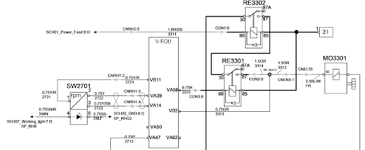
Jika start switch diputar ke START position, arus listrik mengalir sbb :

  • Start switch terminal (B+)
  • Terminal C → Start power relay (RE3302) coil → Ground
  • V-ECU (VA58) → Start relay (RE3301) → Ground

Ketika start power relay dan start relay bekerja :

  • Fuse (FU22, 15A) → Start power relay (RE3302) → Start relay (RE3301) → Start motor relay coil → E-ECU (B29) → E-ECU ground

Starter motor MO3301 disupply langsung dari battery disconnection switch dan memiliki start relay bawaan yang tegangannya dikontroleh oleh control unit E-ECU. Relay RE3301 dikontrol oleh V-ECU ketika start switch SW3301 diputar ke posisi 2.

  1. Starter motor
  2. Terminal 30
  3. Solenoid relay
  4. Terminal 86, +
  5. Terminal 85, E-ECU (EB29)
  6. Terminal 31, ground
  7. Terminal 50

Starter Lock

Starter motor dioperasikan dibatasi secara hati-hat- sehingga fitur antitheft dapat berfungsi.

Input signals

  • VA20 - V-ECU - Control lockout lever, SW9118

Input messages

  • I-ECU - Code lock condition

Parameters

  • ABP - Anti-theft protection

Output signal

  • VA58 - V-ECU - Start motor relay, RE3301

Condition for activation

Jika kondisi berikut terpenuhi, start lock relay RE3301 akan ON.

  • Start switch, ON
  • Control lockout lever, lower position (OFF)
  • If there is anti-theft system option, code lock password must be matched.


Starting Operation - Volvo A60H

Starter Motor

Function description

Ketika ignition switch SW3301 diputar ke posisi dua, starter motor MO3301 diaktifkan oleh control unit HMIM via relay RE06. Setelah engine mulai running, starter motor dimatikan (deactivated).

1. Control cables:
    - from RE06
    - to E-ECU
2. Starter motor relay
3. Ground connection
4. Connection, battery and alternator
5. Solenoid

Jika starter motor telah aktif selama 30 detik dan engine tidak running, E-ECU akan mematikan (deactivated) starter motor dengan menghilangkan grounding via EB29 dan alarm akan dimunculkan pada information display unit.

Amber central warning (kuning) :
- High temp. engine starter motor
- Wait 5 min. before start

Jika engine running atau jika transmission tidak dalam N (neutral) position maka starter motor tidak diaktifkan.

Jika starter motor telah aktif selama 3 detik dan E-ECU tidak mendeteksi engine rpm, starter motor akan dimatikan (deactivated) dan vehicle message akan dimunculkan.

Monitoring, starter motor

E-ECU mengontrol aktivasi dari starter motor sehubungan dengan waktu aktivasi dan risiko overheating.

AL3201 - Alternator
E-ECU - Engine control unit
FUxx - Fuse, circuit board
HMIM - Instrument control unit
JB3101 - Junction box
MO3301 - Starter motor
RExx - Relay, circuit board
SW3301 - Switch, ignition
V-ECU - Vehicle control unit


Engine Control (MR) Function - Mercedes Benz Actros

General information

Engine control (MR) merupakan electronic system yang  independent, yang tugas utamanya untuk mengatur atau mengontrol fungsi fuel injection dari pump-line-nozzle system (PLD system). Hal ini untuk memastikan bahwa engine selalu running pada fuel yang paling efisien, menghasilkan pollutant yang rendah dan emisi suara yang rendah sedapat mungkin dalam semua kondisi operasi.

a) Engine control (MR)
b) Exhaust aftertreatment system
c) Flame starting system (FLA)
d) Drive control (FR)
e) Modular switch panel (MSF)
f) Gear control (GS)
g) Brake control (BS)
h) Instrument (INS)
i) Parameterizable special module (PSM)

CAN 1 Vehicle CAN 
CAN 2 Interior CAN 
CAN 3 Frame CAN 
CAN 4 Engine CAN
CAN 5 Transmission CAN
CAN 6 Brakes CAN
CAN 10 Speedometer CAN
CAN 12 SCR CAN
Z3 Additional CAN star point

A3 Drive control (FR) control unit 
A4 Flame starting system control unit  (FLA)
A6 Engine control (MR) control unit 
- B10 Fuel temperature sensor 
- B11 Engine oil temperature sensor 
- B15 Crankshaft position sensor 
- B16 Camshaft position sensor 
- B65 Coolant temperature sensor 
- B111 Charge air temperature and boost pressure combination sensor 
- S10 Start engine button - up to engine end no. 394441 
- S10.1 Start engine button/Stop engine button  - As of engine end no. 394442 
- S11 Stop engine button - up to engine end no. 394441
- Y6 Cylinder 1 unit pump 
- Y7 Cylinder 2 unit pump 
- Y8 Cylinder 3 unit pump 
- Y9 Cylinder 4 unit pump
- Y10 Cylinder 5 plug-in pump
- Y11 Cylinder 6 plug-in pump
A7 Base module (GM) 
A11 Electronic brake system (EBS) control unit 
A16 Gear control (GS II) control unit 
A22 Parameterizable special module
A28 Drive axle, axle modulator 
A42 Immobilizer read-out electronics
- S1 Drive switch
- 0 Ignition OFF
- 1 Circuit 15R ON
- 2 Circuit 15 ON
- 3 Circuit 50
- 4 ASIC data bus
A68 Master switch module 4 
A78 Dash support switch module 3 
A95 SCR frame module control unit 

Engine control (MR) control unit (A6) megkalkulasi awalan injection sesuai kondisi operasi dari engine dan specified torque  dari drive control (FR) serta injection quantity yang dibutuhkan untuk pembakaran. Engine control (MR) control unit (A6) juga memastikan fuel diinjeksikan pada saat yang tepat dan dalam jumlah yang tepat ke dalam cylinder melalui pengaktifan solenoid valve pada unit pump.

Sedangkan parameter yang berhubungan dengan kualitas consumption, performance dan exhaust gas dideteksi oleh charge air temperature and boost pressure combination sensor (B111), fuel temperature sensor (B10) serta coolant temperature sensor (B65).  Engine control (MR) control unit (A6) mendeteksi current rotational speed serta pergerakan piston relatif terhadap top dead center (engine position) melalui crankshaft position sensor (B15) dan siklus compression stroke pada cylinder 1 melalui camshaft position sensor (B16).

Torque spesifik yang diminta oleh drive control (FR) control unit (A3) dikalkulasi dari sejumlah input termasuk posisi foot throttle actuator (A3) melalui engine CAN (CAN 4) ke drive control (MR) control unit (A6).

Kondisi operasi dari engine ditentukan berdasarkan nilai input dari sensor-sensor berikut ini :

  1. Crankshaft position sensor (B15)
  2. Camshaft position sensor (B16)
  3. Charge air temperature and boost pressure combination sensor (B111)
  4. Fuel temperature sensor (B10)
  5. Coolant temperature sensor (B65)

K2 Battery disconnect switch
M1 Starter
P2 Instrument (INS)
P3 Modular tachograph (MTCO)


22 October 2023

Powertrain - Volvo A60H

Powertrain

Power dari engine sampai ke wheel disalurkan secara hydraulic dan mechanic menuju transmission melalui flywheel dan torque converter. Dari sini power diteruskan ke dropbox yang kemudian didistribusikan axle. Dari masing-masing final drive (differential carrier assembly) the power kemudian didistribusikan ke wheel hub.

  1. Engine
  2. Power take-offs for hydraulic pumps
  3. Transmission
  4. Propeller shaft between transmission and dropbox
  5. Dropbox
  6. Propeller shaft in steering joint
  7. Intermediate shaft in frame joint
  8. Propeller shaft between frame joint and front bogie axle
  9. Propeller shaft between front bogie axle and rear bogie axle
  10. Rear bogie axle
  11. Front bogie axle with power divider (splitter box) to rear bogie axle
  12. Propeller shaft between dropbox and front axle
  13. Front axle

Flywheel housing

Antara engine dan torque converter terdapat flywheel housing dan power take-off (PTO) untuk menggerakan hydraulic pump. Flex plate yang terletak pada flywheel housing menerusakan power ke torque converter didalam transmission melalui vibration damper.

Torque converter

Torque converter memiliki free-wheel stator dan direct clutch (Lock-up) and menyesuaikan torsi sesuai kebutuhan.

Transmission

Transmission dengan planetary type dan automatic penuh dengan 6 forward gears dan 2 reverse gears. Lock-up tersedia dalam semua gear. Automatic shifting dikontrol oleh electronic control unit (T-ECU) untuk selalu memilih gear yang tepat sesuai speed dan torque.

Dropbox

Dropbox memiliki 2 gear dan differential dengan fungsi lock. Ground-dependent hydraulic pump untuk secondary steering system juga terletak pada dropbox. Dropbox digerakan oleh transmission melalui propeller shaft untuk menggerakkan front axle dan rear drive axles.

Drive shafts

Drive axle memiliki transverse differential dengan differential lock dan planet gear pada hubs. Front bogie axle memiliki dog-clutch.

Parking Brake, Manually Releasing - Volvo A60H

Parking brake, manually releasing

Parking brake dapat di-released secara manual jika tidak dapat di-released melalui switch atau ketika tidak ada accumulator pressure. Parking brake harus selalu di-released secara mekanikal jika tidak memungkinkan untuk ditarik (towing) dengan kondisi engine running.

  • Mechanical release of parking brake
    • Pasang ganjal pada roda untuk mencegah machine bergerak.
    • Lepas protective caps dari adjusting screws pada semua parking brake caliper.


    • Release parking brake dengan memutar adjusting screws berlawanan arah jarum jam (counter-clockwise) sampai screw sejajar dengan tepi luar dari brake caliper.


      1. Outer edge of brake caliper

NOTE!

JIka machine ditinggal dalam kondisi mechanically released parking brake, pasang service tag pada steering wheel yang menginformasikan parking brake tidak berfungsi.

Materi terkait :

Engine, Sensor Location - Volvo A60H

Introduction

Engine six-cylinder segaris, four-stroke, direct-injected diesel engine. Memiliki empat valve per cylinder dan single overhead camshaft. Engine D13F dan D16F dilengkapi dengan single turbocharger beserta wastegate dan engine D11F memiliki turbocharger tanpa wastegate. Engine dilengkapi pula dengan engine brake, VEB+ (Exhaust Pressure Governor danVolvo Compression Brake). 

Ini menggambarkan sensor yang terdapat pada engine. Pada beberapa versi engine, letak dan jumlahnya dapat berbeda.


Gambar untuk D16J

  1. Sensor, fuel pressure, SE2301
  2. Sensor, temperature intercooler (charge-air cooler), SE2512. Applies to D16J.
  3. Sensor, charge-air temperature, SE2507, Sensor, boost pressure, SE2508
  4. Monitor, coolant level, SE2603
  5. Monitor, water in fuel, SE2302
  6. Sensor, crankcase pressure, SE2509
  7. Sensor, engine oil level, SE2205 Sensor, engine oil temperature, SE2202
  8. Sensor, engine oil pressure, SE2203
  9. Sensor, engine speed, SE2701
  10. Sensor, coolant temperature, cooling circuit transmission/brakes, SE2601


Gambar untuk D16J

  1. Sensor, ambient air temperature SE2501, monitor air filter pressure SE2502
  2. Sensor, exhaust gas recirculation, pressure (EGR) SE2515. Applies to D16J.
  3. Sensor, camshaft speed, SE2703
  4. Sensor, turbo speed, SE2514. Applies to D16J.
  5. Sensor, coolant temperature engine, SE2606
  6. Sensor, exhaust gas recirculation, temperature (EGR) SE2516. Applies to D16J.
  7. Sensor, exhaust back-pressure, SE2511. Applies to D16E and D16F.
  8. Sensor, coolant temperature, cooling circuit engine SE2602
  9. PWM-valve, control exhaust recirculation (EGR). Applies to D16J.

Engine protection
E-ECU didesain memiliki fungsi untuk melindungi engine dari kerusakan selama beroperasi dengan extreme condition atau kerusakan yang lebih parah ketika engine component mengalami kegagalan atau kerusakan. Komponen yang dapat meminta mode engine protection adalah :
  • High coolant temperature
  • High inlet manifold air temperature
  • High oil temperature
  • Low oil pressure
  • Low coolant level
  • High crankcase pressure
  • High compressor charge-air temperature (calculated)
  • High E-ECU temperature
  • High Altitude (ensures that high compressor charge-air temperature is never reached)

Auxiliary Brake (Engine Braking) - Volvo A60H

A60H Volvo

Engine brake VEB adalah singkatan dari Volvo Engine Brake. VEB tersedia dalam beberapa versi, dan berikut ini menjelaskan fungsi tersebut untuk articulated hauler. Engine brake terdiri dari dua subsystem yaitu :

  1. Exhaust brake, VGT (Variable Geometry Turbo) alternatif lainnya Exhaust brake, EPG (Engine Pressure Governor)
  2. Compression brake, VCB (Volvo Compression Brake)

Engine Brake Function

Ketika VEB diaktifkan, exhaust stroke dan compression stroke digunakan untuk meningkatkan engine's braking power. Pada saat yang bersamaan fuel injection dimatikan.

A. Exhaust stroke digunakan dimanfaatkan dengan exhaust pressure governor shutter menutup jalur outlet yang berasal dari turbocharger. Ketika piston bergerak naik (TDC), tekanan balik tinggi tercipta didalam cylinder dan berdampak pada braking effect, karena gas buang tidak dapat dikeluarkan dengan cara yang sama seperti engine running dalam kondisi normal. Exhaust pressure governor dikontrol oleh control valve PWM2501 dan dapat berfungsi karena adanya udara bertekanan. 

  1. Compressed air cylinder
  2. Damper housing
  3. Connection exhaust back-pressure, sensor SE2511 / SE2518


AVU (Air Valve Unit) tersedia dalam 2 variant :
A) Twin-port AVU valve : mengatur EPG dan turbocharger bypass valve.
B) Single-port AVU valve :hanya mengatur EPG pada engine yang turbocharger yang tidak memiliki bypass
valve.

B. Compression stroke digunakan untuk meningkatkan braking power (effect). High pressure pada exhaust manifold digunakan selama exhaust braking. Di sekitar posisi BDC setelah inlet stroke, exhaust valve membuka sebentar agar tekanan tinggi masuk mengisi ke dalam cylinder. Pada compression stroke selanjutnya, tbraking power (effect) akan lebih tinggi dikarenakan "pengisian" yang terjadi sebeumnya.

  1. Oil inlet
  2. Oil outlet
  3. Solenoid valve

C. Pada akhir compression stroke exhaust valve membuka seketika untuk melepaskan udara bertekanan (decompression). Dengan cara ini efek dorongan selama power stroke dapat dihindari, yang jika tidak maka akan mengurangi engine braking effect.

NOTE!

Ketika menggunakan switch untuk engine brake bersamaan dengan melepas accelerator pedal, engine brake function tergantung pada engine type.

Principle illustration, two cam profiles

Engine brake function, principle illustration

A. Exhaust stroke
B. Compression stroke
C. Decompression

Materi terkait :


Load and Dump Brake - Volvo A60H

Introduction

Fungsi dari Load and Dump brake adalah untuk mempermudah pengoperasian semua wheel brake ketika loading dan dumping. Tujuannya adalah untuk menghindari penggunaan parking brake yang tidak diperlukan ketika loading dan dumping. Fungsi ini aktif olehrocker-switch (SW5901) yang terletak pada dump lever console, dan menjadi tidak aktif ketika gear selector digerakan dari neutral position (N). Ketika Load and Dump brake aktif diindikasikan dengan control light pada instrument panel.


Function description

Activation

Kondisi berikut harus terpenuhi untuk dapat mengaktifkan Load and Dump brake.

  • Engine is ON
  • Machine speed is below 6 km/h (3,7 mph)

Brake control block

  1. Pressure check connection AM1
  2. PWM5203 for brake control
  3. Checking point M15
  4. SE5203 pressure sensor

Ketika switch SW5901 diaktifkan, brake pressure dinaikan melalui PWM5203 sampai wheel brake aktif (applied). Dan juga gear posisi Neutral, sehingga control light untuk Load and Dump brake menyala. Pengaturan PWM5203 mendapatkan feedback dari sensor SE5203 melalui ECU untuk mencapai tingkat tekanan yang lebih seragam.

Jika Load and Dump brake aktif dan brake pressure yang bekerja pada tractor unit atau load unit mengalami penurunan dibawah 52 bar, maka parking brake akan aktif.

Deactivation

Untuk mematikan Load and Dump brake, gear selector harus dipindahkan dari posisi Neutral ke posisi lainnya. Ketika V-ECU mendeteksi bahwa transmission dan dropbox telah masuk gigi, maka wheel brake akan di-released dan control light untuk Load and Dump brake akan padam.

Jika Load and Dump brake aktif dan start key diputar ke 0 atau R, system akan menunggu sampai parking brake diaktifkan dan wheel brake aktif kemudian control light untuk Load and Dump brake akan padam.

Function diagram

  • SE5201, sensor, feed pressure brakes, tractor unit
  • SE5202, sensor, charge pressure brakes, trailer unit
  • SE5203, sensor, deployed brake pressure, tractor unit
  • SE5226, sensor input pressure from pump
  • PWM5203, brake control valve
  • MA5501, control of parking brake
  • SE5501, sensor for pressure on parking brake

Materi terkait :


Retarder - Volvo A60H

Function

Retarder berfungsi untuk mempermudah pengoprasian wheel brake ketika dalam kondisi turunan (downhill) dan meminimalkan resiko terjadinya overheating pada wheel brake. Fungsi retarder terintegrasi dengan standard wheel brake. Fungsi retarder diaktifkan oleh retarder pedal. Ketika retarder pedal digunakan dan accelerator pedal dilepas. Ketika retarder pedal diaktifkan, yang pertama terjadi adalah permintaan untuk pengaktifan engine brake kemudian wheel brake akan diaktifkan jika diperlukan. Peningkatan dan penurunan penggunaan engine brake sejalan dengan pergerakan pedal.

Jika brake mulai mengalami overheat, fungsi retarder akan secara otomatis mengurangi brake pressure yang diperlukan. Brake pressure dikurangi secara proporsional berdasarkan brake cooling oil temperature, dimulai pada 115 °C (239 °F) dan  100% pada 120 °C (248 °F). Penting untuk mengurangi kecepatan jika brake mengalami overheated. Feed pressure untuk PWM5203 diberikan dari accumulator circuit.

Brake control block

Sensor untuk retarder pedal position, SE4208 terletak pada retarder pedal dan terdiri dari dua circuit yaitu primary dan a secondary. Hal ini bertujuan untuk memastikan retarder pedal position dikalkulasikan seakurat.


  1. Pressure check connection AM1 common accumulator pressure
  2. PWM5203 brake control valve
  3. Pressure check connection M15, deployed brake pressure tractor unit
  4. SE5203 pressure sensor deployed brake pressure tractor unit

Vehicle message akan muncul jika :

  • Malfungsi terdeteksi pada the primary circuit
  • Malfungsi terdeteksi pada secondary circuit
  • Jika terdapat deviasi nilai antar circuit lebih dari 10%

Function diagram

  • SE5201, sensor accumulator pressure brakes, tractor unit
  • SE5202, sensor accumulator pressure brakes, load unit
  • SE5203, sensor, deployed brake pressure, tractor unit
  • SE5226, sensor common accumulator pressure
  • PWM5203, brake control valve
  • MA5501, control of parking brake
  • SE5501, sensor, pressure parking brake

Parking Brake - Volvo A60H

Parking Brake

Parking brake memiliki tiga buah brake caliper yang bekerja dengan menggunakan gaya spring dan release menggunakan  energy hydraulic. Ketika parking brake terpasang (aktif), differential lock pada dropbox jug aktif (engaged) yang dimunculkan pada information display.

Parking brake diaktifkan oleh operator menggunakan two-position switch. Untuk tujuan kemanan, parking brake dapat juga terpasang secara automatic misalnya pada kasus low accumulator pressure pada brake circuit. Saat menstarter machine, parking brake selalu diaktifkan, apapun posisi parking brake switch. Jika switch berada pada posisi “released”, switch r harus dipindahkan ke posisi “activated” dan kemudian kembali ke posisi “released” untuk melepas Parking brake.

Gear berpindah ke neutral position sesaat setelah parking brake terpasang (aktif), kecuali brake pedal atau accelerator pedal diaktifkan. 

Parking Brake Applied (aktif)

Parking brake applied, function diagram

  1. Hydraulic pump, P6
  2. Switch for parking brake, SW5501
  3. Solenoid valve for controlling hydraulic pressure to parking brake cylinders, MA5501
  4. Pressure sensor for checking hydraulic pressure to parking brake cylinders, SE5501
  5. Parking brake with hydraulic brake calipers
  6. Differential lock in dropbox.
  7. Solenoid valve for controlling differential lock (released when pressurized) in the dropbox, MA4604.
  8. Solenoid valve for draining air pressure for applying differential lock in the dropbox, MA4606.
  9. Compressed air tank
  10. Compressed air compressor

Parking Brake Deactivated (tidak aktif)

Untuk me-release parking brake, operator harus menggerakan two-position switch SW5501 dari position “applied” ke position “released”. Input VB55 dan VB89 pada control unit V-ECU mendeteksi posisi two-position switch, SW5501. Ketika switch diposisikan “applied” tidak ada voltage pada output VB49 dan solenoid valve MA5501 mengalirkan hydraulic pressure dari parking brake cylinder menuju ke tank.

Ketika switch SW5501 dipindah dari “applied” ke “released” dan kondisi release the parking brake terpenuhi, solenoid valve MA5501 disupply tegangan melalui output VB49 pada control unit V-ECU.

Ketika solenoid valve MA5501 diaktifkan, parking brake cylinder diberi tekanan dan parking brake di-released. Pada saat yang sama MA4606 diaktifkan dan differential lock pada dropbox di-released. Ketika pressure sensor SE5501 mengindikasikan tekanan diatas 190 bar (2755 psi), parking brake di-released dan parking brake light dimatikan.

Parking brake released, function diagram

  1. Hydraulic pump, P6
  2. Switch for parking brake, SW5501
  3. Solenoid valve for controlling hydraulic pressure to parking brake calipers, MA5501
  4. Pressure sensor for checking hydraulic pressure to parking brake calipers, SE5501
  5. Parking brake with hydraulic brake calipers
  6. Differential lock in dropbox.
  7. Solenoid valve for controlling differential lock (released when pressurized) in the dropbox, MA4604.
  8. Solenoid valve for draining air pressure for applying differential lock in the dropbox, MA4606.
  9. Compressed air tank
  10. Compressed air compressor

NOTE!

Jika parking brake di-released melalui switch dan pressure sensor SE5501 tidak mendeteksi tekanan diatas 190 bar setelah  3 detik, parking brake diaktifkan kembali.

Materi terkait :

Hydraulic Brake System - Volvo A60H

Service Brake

Semua axles dilengkapi dengan multi-disc brake tipe basah yang terpisah dengan brake cooling. Service brake beroperasi secara hydraulic. Hydraulic pump digunakan untuk mengisi tekanan brake system (brake charging) dan juga untuk menggerakan engine radiator fan. Pengisian tekanan brake system (memiliki prioritas. Rear brake circuit dioperasikan melalui relay valve pada beban unit untuk mendapatkan respons yang lebih cepat.

  1. Brake cooling valve
  2. MA5503 Shut-off, cooling fan
  3. PWM5201 Circulation, brake cooling oil
  4. Accumulator bank, front brake circuit
  5. SE5226 Sensor, feed pressure common brake circuit
  6. M21 Charge pressure brakes, tractor unit
  7. SE5201 Sensor, feed pressure brakes, tractor unit
  8. M22 Feed pressure load unit (trailer)
  9. SE5202 Sensor, feed pressure brakes, trailer unit
  10. Pressure oil filter, brake system
  11. Brake control block
  12. AM1 Feed pressure, common brake circuit
  13. PWM5203 Brake control valve
  14. SE5203 Sensor, deployed pressure brakes, tractor unit
  15. Measuring ramp
  16. M11 Brake cooling circuit, tractor unit
  17. M12 Brake cooling circuit, load unit (trailer)
  18. M29 (Hydraulic Suspension, HS)
  19. Foot brake valve
  20. M15 Deployed brake pressure, tractor unit
  21. Hydraulic pump P6
  22. Hub with disc brake

  1. Relay valve, rear brake circuit
  2. Air vent valve
  3. M16 Deployed brake pressure load unit (trailer)
  4. Accumulator bank, rear brake circuit
  5. Air vent valve
  6. SE5501 Sensor, parking brake
  7. MA5501 Solenoid valve parking brake
  8. Accumulator bank, rear brake circuit
  9. Air vent valve
  10. Parking brake
  11. Breather, wheel brake
  12. Brake pipe

  1. Accumulator, common circuit
  2. SE5226 Sensor, feed pressure common brake circuit
  3. Connection to P6
  4. Pressure check connection M21, feed pressure tractor
  5. SE5201 Sensor, feed pressure brakes, tractor unit
  6. Accumulator, feed circuit tractor unit
  7. Non-return valve common circuit/tractor unit brake circuit
  8. Non-return valve common circuit/load unit (trailer) brake circuit
  9. Connection to accumulator bank on load unit (trailer)
  10. Accumulator, feed circuit load unit (trailer)
  11. SE5202 Sensor, feed pressure brakes, trailer unit
  12. Connection to rear circuit brake pedal
  13. Connection to front circuit brake pedal
  14. Pressure check connection M22 Feed pressure load unit (trailer)

Front brake circuit dan rear brake circuit memiliki accumulator bank yang terpisah. Accumulators telah diisi sebelumnya dengan nitrogen yang berfungsi untuk menyimpan energy guna memastikan kemampuan pengereman yang baik bahkan jika brake charging mengalami kegagalan. Central warning aktif dan parking brake terpasang jika accumulator pressure menjadi terlalu rendah.


Selain aktivasi melalui brake pedal, wheel brake dapat juga diaktifkan melalui PWM 5203 yang terletak pada brake control block yang memiliki fungsi seperti berikut ini :

  • Automatic brake

Automatic brake melindungi engine dan transmission dari terjadinya overspeeding. Ketika engine overspeed terdeteksi, maka warning akan muncul kemudian wheel brake akan diaktifkan. Fungsi ini juga akan aktif ketika max. speed melebihi batas.

  • Load and dump brake

Fungsi load and dump brake terintegrasi dengan dengan standard wheel brake system. Fungsi ini untuk mengurangi keausan dari parking brake dan drivetrain dengan mengaktifkan semua wheel brake selama loading dan dumping. Fungsi ini diaktifkan oleh switch SW5901 pada dump lever. 

  • Hill Assist

Fungsi Hill Assist adalah untuk mencegah machine dari pergerakan yang tidak diinginkan (rolling) ketika pada kondisi tanjakan.

  • Retarder function

Fungsi retarder function memungkinkan pengoperasian wheel brake ketika unit beroperasi pada kondisi turunan (downhill) dan meminimalkan terjadinha resiko overheating pada wheel brake. Retarder dioperasikan dengan menggunakan retarder pedal. 


Function diagram

  • SE5201, sensor accumulator pressure brakes, tractor unit
  • SE5202, sensor accumulator pressure brakes, load unit
  • SE5203, sensor, deployed brake pressure, tractor unit
  • SE5226, sensor common accumulator pressure
  • PWM5203, brake control valve
  • MA5501, control of parking brake
  • SE5501, sensor, pressure parking brake

Catatan :
Untuk Volvo A45G ada sedikit perbedaan lokasi dan komponen.

Materi terkait :

Wheel Brake - Volvo Truck

Pergerakan brake shoe dikontrol oleh sebuah mekanisme yang disebut "Z eccentric". Huruf "Z" mewakili bagaimana tekanan pada pin yang terletak pada shaft dan cam. Ketika shaft dan cam diputar, pressure pin terdorong keluar. Pergerakan ini diteruskan ke brake shoe oleh tappet head. Lakukan penyetelan dengan memutar adjusting screw sehingga tappet heads bergerak keluar. Primary dan secondary brake shoe berbeda bentuk dan tidak dapat dipasang terbalik. 

  1. Shaft with cam
  2. Pressure pins
  3. Adjuster screw
  4. Tappet head
  5. Pins
  6. Return spring

P Primary shoe
S Secondary shoe

Selama proses braking (pengereman), secondary shoe bergerak sedikit menyentuh brake drum sebelum primary shoe. Hal ini terjadi supaya secondary shoe terdorong kebelakang sedangkan primary shoe tertarik searah putaran brake drum.

A Eccentric side end
B Support block side end

Adjustment Mechanism

Mekanisme penyetelan tersusun dalam housing agar terlindung dari kotoran dan kelembaban. Brakes bisa jadi di-adjust secara otomatis ataupun manual. Pada automatic adjusting system, brake di-adjust ketika keausan lining mencapai level tertentu. Adjusting screw terhubung terhadap secondary shoe adjusting screw oleh cross shaft. Selama penyetelan, screws berputar perlahan dan tappet head bergerak sedikit.

  1. Pinion
  2. Tappet head
  3. Adjuster screw
  4. Cross shaft

Confined Space Entry Permit

Surat Ijin Bekerja Di Ruang Terbatas/Tertutup (Confined Space Entry Permit) adalah suatu dokumen untuk mengontrol personel yang akan masuk ke dalam confined space dengan tujuan kehatian-hatian agar tidak terjadi kecelakaan. Surat izin ini harus ditanda tangani oleh personel yang berwenang, yang merupakan bagian dari prosedur keselamatan bekerja di confined space. 

Kegunaan dari surat izin masuk confined space adalah sbb :

  1. Memastikan bahwa otorisasi yang tepat telah diperoleh
  2. Memastikan bahwa manajemen mengetahui semua yang masuk ke confined space
  3. Untuk mengecek bahwa tempat pekerjaan sudah aman sebelum memulai pekerjaan
  4. Mendapatkan informasi tentang potensi bahaya yang didalamnya
  5. Memastikan bahwa tidak ada pekerjaan diluar yang dapat mempengaruhi orang yang bekerja didalam confined space

Surat Ijin Bekerja Di Ruang Terbatas/Tertutup (Confined Space Entry Permit) harus memuat hal-hal berikut ini :

  • Detail Pekerjaan

    1. Nama-nama orang yang diberi ijin kerja
    2. Uraian pekerjaan yang akan dilakukan
    3. Lokasi pekerjaan
    4. Tanggal dikeluarkan ijin
    5. Jam dikeluarkan ijin
    6. Periode berlakunya ijin

  • Persyaratan Keselamatan

    1. Melakukan Inspeksi area kerja sebelum pekerjaan dimulai
    2. Self Contained Breathing Apparatus /SCBA tersedia (Sesuai hasil tes gas)
    3. Airline Respirator tersedia (Sesuai hasil tes gas)
    4. Combined Organic Vapor and Particulate Filter Respirator tersedia (Sesuai hasil tes gas)
    5. Disposable Respirator tersedia (Sesuai hasil tes gas)
    6. Area kerja telah diperiksa, diamankan, dibersihkan, didemarkasi, dan diventilasi
    7. Benda/mesin/peralatan/instalasi (termasuk peralatan listrik) telah diisolasi (dipasang lock out & tag out)
    8. Peralatan kebakaran dan kedaruratan tersedia dan pekerja telah memahami prosedur kedaruratan
    9. Pekerja yang terlibat telah terlatih/memiliki kompetensi sesuai dengan pekerjaan yang akan dikerjakan
    10. Job Safety Analysis (JSA) tersedia dan memadai (lampirkan)
    11. Job Safety Analysis (JSA) telah disosialisasikan kepada semua pekerja yang terkait
    12. Peralatan komunikasi tersedia (2–ways communication) (HP/Radio)
    13. Terdapat observer pada akses masuk (man hole) yang mengawasi kegiatan di dalam ruang
    14. Melakukan inspeksi area kerja setelah pekerjaan selesai dilakukan

  • Data Hasil Pengukuran Gas

    1. Gas mudah terbakar (flamable)
    2. Methane
    3. Oxygen
    4. Carbon Monoxide
    5. Hydrogen Sulfide
    6. Hydrogen Cyanide
    7. Gas lainnya

  • Rencana Penanganan Keadaan Darurat
Menurut OSHA, perencanaan tanggap darurat minimal harus mencakup hal-hal sebagai berikut:
  • Prosedur pelaporan kecelakaan atau keadaan darurat lainnya
  • Kebijakan dan prosedur evakuasi, mencakup jalur evakuasi,  tim evakuasi (floor warden) atau sarana evakuasi lainnya.
  • Skema atau daftar nomor telepon penting yang harus dihubungi saat keadaan darurat
  • Prosedur tindakan darurat mulai dari pra kejadian, saat terjadi keadaan darurat, dan pasca kejadian.  Prosedur juga mencakup pembahasan tentang peralatan darurat, peralatan pemadam kebakaran, alarm, peralatan P3K, hingga prosedur emergency shutdown. 
  • Susunan tim tanggap darurat mencakup koordinator, tim evakuasi, petugas P3K, dan petugas lain yang diperlukan.
  • Penentuan lokasi tempat berkumpul (assembly point) dan prosedur pelaporan yang menyatakan bahwa semua pekerja sudah dievakuasi juga perlu dipertimbangkan.
  • Pernyataan Pengawas
  • Persetujuan Pemberi Ijin Kerja

21 October 2023

Faktor Yang Mempengaruhi Engine Horsepower

Selain dari parameter-parameter dasar yang dapat mempengaruhi tenaga (power) engine yaitu : 
  1. Diameter dalam silinder (bore) 
  2. Panjang langkah piston (stroke) 
  3. Volume (displacement) 
  4. Perbandingan kompresi (compression ratio)
Ada faktor-faktor lain yang mempengaruhi engine horsepower diantaranya oleh 3 unsur utama : 
  1. Panas (compression ratio)
  2. Udara 
  3. Fuel (Bahan bakar)
Seperti yang sudah kita ketahui bahwa ketiga hal tersebut adalah termasuk kedalam segitiga api, yang erat kaitannya dengan internal combustion engine. Engine akan mencapai rated horsepower bila memenuhi beberapa kondisi pengetesan pabrik yang didasari standard internasional SAE-J1995 (Engine Power Test Code - Spark Ignition and Compression Ignition - Gross Power and Torque Rating).


Udara
Kondisi udara yang dapat mempengaruhi horsepower engine diantaranya : 
  • Atmospheric Conditions 
Merupakan kondisi tekanan udara sekitar yang sangat tergantung kepada ketinggian daerah operasi engine terhadap permukaan laut. Semakin tinggi suatu daerah dari permukaan laut maka semakin sedikit jumlah udaranya sehingga tekanannyapun semakin rendah, sebaliknya semakin dekat suatu daerah dari permukaan laut maka semakin banyak jumlah udaranya dan tentunya tekanannya pun semakin besar. Semakin besar tekanan udara sekitar, jumlah udara yang dapat masuk kedalam silinder juga semakin banyak dan semakin sempurna pembakaran yang terjadi.

  • Air Inlet Temperature 

Semakin tinggi temperature udara berakibat semakin sedikit molekul-molekul udara yang masuk kedalam ruang bakar. Hal ini secara langsung mengakibatkan penurunan horsepower engine, disamping itu kenaikan 1°F air inlet mengakibatkan naiknya exhaust temperature sebesar 3°F. 

Fuel
Kondisi fuel yang dapat berpengaruh terhadap engine diantaranya : 
  • Specific Gravity Diesel Fuel 
Adalah berat fuel dengan jumlah tertentu dibandingkan dengan berat air dengan jumlah dan pada temperature yang sama. Semakin tinggi specific gravity berarti semakin berat fuel tersebut dan semakin besar energi atau horsepower yang dapat dihasilkan engine. Specific gravity dapat diukur menggunakan fuel hydrometer. Fuel yang ringan tidak akan menghasilkan horsepower maksimum tanpa dilakukan penyetelan pada fuel system, namun untuk mengkompensasi kondisi tersebut, penyetelan fuel system tidak diperbolehkan karena umur komponen fuel system dapat menurun akibat berkurangnya efek pelumasan. Fuel yang terlalu berat mengakibatkan banyaknya deposit pada combustion chamber, sehingga dapat menimbulkan keausan yang tidak normal pada liner dan piston ring. 

  • Fuel Temperature

Kenaikan temperature fuel pada daerah antara transfer pump dan fuel injection pump atau injector dapat mempengaruhi kemampuan engine. Kenaikan temperature ini dapat disebabkan oleh radiasi panas dari komponen engine lainnya atau karena terhambatnya aliran return fuel ke tangki. Semakin tinggi temperature fuel maka spesific gravity- nya akan semakin rendah dan nilai panas yang terkandung didalam fuel menjadi berkurang. Disamping berpengaruh terhadap horsepower, temperature fuel yang akan masuk ke fuel injection pump atau fuel gallery juga sangat berpengaruh terhadap viscosity.

  • Fuel Viscosity 

Viscosity merupakan ukuran dari hambatan cairan untuk mengalir. Viscosity tinggi berarti fuel terlalu kental dan tidak akan mengalir dengan mudah. Fuel dengan viscosity yang salah (terlalu kental atau terlalu cair) dapat mengakibatkan kerusakan engine. Viscosity fuel yang terlalu tinggi dapat meningkatkan keausan pada gear train, cam dan follower fuel injection pump karena semakin tingginya injection pressure. Viscosity fuel yang terlalu rendah tidak dapat menyediakan pelumasan yang baik pada plunger, barrel dan injector. Pengabutan fuel juga semakin tidak baik dan engine susah distart. Salah satu cara mengubah viscosity fuel adalah dengan memanaskan atau mendinginkan fuel.

Electronic Air Drier - Volvo Truck

Air Drier, General Electronic air drier bekerja berdasarkan prinsip yang sama seperti pendahulunya yang dikontrol udara. Perbedaannya, e...